
Define the air-path working point before comparing models
A miniature air pump should be compared against the condition it will see in the equipment, not against a free-flow number on a catalog page. Start by recording the medium, target flow, required pressure or vacuum, supply voltage, duty cycle, available envelope and port arrangement. Then add the tubing inner diameter and length, filter grade, valve state, fittings and the final chamber or outlet. These details turn a general request for a miniature air pump into a testable operating point.
For a controlled bench check, an OEM team might hold a 24 V DC supply, 4 mm inner-diameter tubing, 1.2 m total tube length, an inlet filter and a normally closed solenoid valve in the same setup used for the first comparison. The purpose is not to make those values universal. The purpose is to keep the test state visible. If the pump is first measured with an open outlet and later installed behind a filter and valve, the two results should not be treated as the same specification.
Read flow and pressure as one requirement
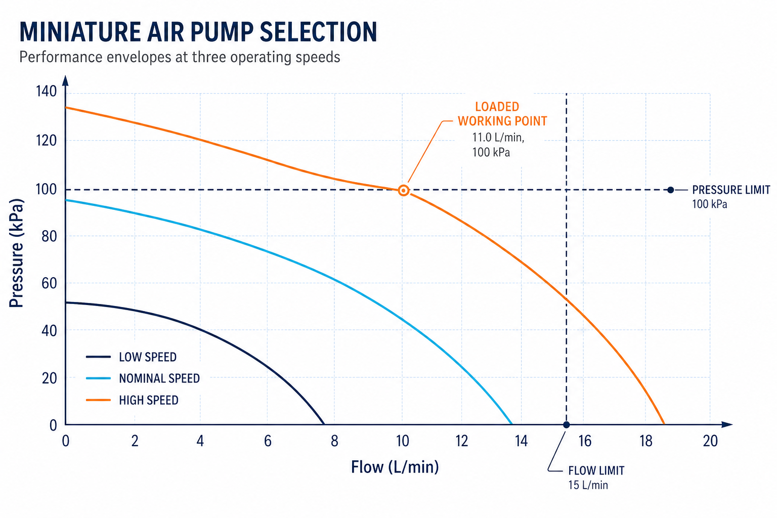
Maximum flow and maximum pressure are usually boundary points, not one simultaneous operating condition. Maximum flow is normally measured with very little resistance. Maximum pressure or vacuum is reached when flow has fallen close to zero. An OEM air path usually operates between those limits, so a useful miniature air pump selection asks for flow at a stated back pressure or vacuum level. A curve, a measured operating point or a defined acceptance table is more useful than a single headline value.
For a pressure-supply circuit, define the flow that must remain available after the regulator, valve and outlet restriction. For a vacuum circuit, define the flow that remains at the target negative pressure and include leakage from the chamber, seal and fittings. The same miniature air pump may look suitable for an open-flow requirement but fail once the equipment needs pressure to build quickly. State both axes in the request so the supplier can compare the pump at the same load.
Leave a margin that has a reason behind it. Filter loading, supply-voltage tolerance, ambient temperature and assembly variation can all move the working point. A margin should be checked against the actual curve and the equipment limit; it should not be a random percentage added after the model has already been chosen.
Add tubing, filter and valve loss to the selection
Small air paths are sensitive to restrictions. A narrow tube, a long bend, a sharp fitting, a fine filter or a valve with a small effective port can consume a large part of the available pressure. The loss may not be obvious when the pump is tested alone, yet the instrument can show slow evacuation, weak pressure recovery or a flow reading that changes after the filter has been used for a period of time. Treat the pump, tube, filter, valve, sensor and outlet as one fluid path.
Record the total tube length rather than only the nominal hose size. Include the shortest bend radius, reducer, tee, quick connector and any section that can collapse under vacuum. For an inlet filter, record clean pressure drop and the expected loaded condition. If the filter is a service part, check that its replacement does not change the validated tube length or introduce a different port restriction.
A practical review uses measurement points before and after the highest-loss component. Comparing those readings helps separate pump capability from a clogged filter, a sticking valve or a damaged tube. This is especially useful when a prototype passes on the bench but misses flow after it is placed inside the equipment enclosure.
Choose the pump architecture from medium and response
Pump architecture should follow the medium, pressure range, response requirement and service environment. A diaphragm air pump is often considered for clean air transfer, sampling and vacuum generation because the fluid path can be separated from the drive side. A piston pump or compact compressor may be a better starting point when the application is dominated by pressure supply, fast pressure build or a different pneumatic response. Neither choice is automatically better; the comparison must use the same flow, pressure, voltage and duty cycle.
Check the details that change the result within the same family: valve layout, motor speed, chamber volume, port size, wetted material, mounting direction and control method. If the air contains condensate, particles or a process gas, document the medium and filtration condition before requesting a configuration. A miniature air pump selected without that information can pass a short open-flow test and still need a different material or valve configuration for the equipment.
Treat low noise as a system result
A low noise air pump is not defined by the pump alone. Motor commutation, diaphragm or piston pulsation, inlet turbulence, outlet restriction, bracket resonance and enclosure panels can all be audible. A pump that seems quiet in free air may excite the equipment shell after mounting. Conversely, a hose section or chamber volume can reduce one frequency while increasing another. The noise requirement should therefore state the measurement position, operating load, distance, mounting condition and whether the enclosure is installed.
Measure at the user position and at the enclosure surface during the same flow and pressure test used for performance validation. If the result is outside the limit, check the mounting interface, fastener preload, tubing contact, air-path pulsation and motor control before changing the pump. The fix may be an isolation detail, a revised routing or a different operating speed rather than a larger pump.
Check duty cycle, current and thermal limits
A pump that meets the working point for a few minutes may not meet the same point over the equipment duty cycle. Record startup current, running current, supply-voltage range, run time, rest time, ambient temperature and the temperature near the pump and motor. An enclosure with limited airflow can create a different thermal condition from an open bench. Temperature rise should be reviewed together with pressure, flow and current because a change in load can move all three.
Include restart behavior after the normal rest interval and after the warmest expected condition. For speed-controlled versions, define the control signal, minimum stable speed and the behavior when the load changes. Do not use current as a substitute for performance: a lower current can accompany insufficient pressure, while a higher current can indicate a restriction or a configuration that is operating too close to its limit.
Build a validation matrix in the final enclosure
The final validation matrix should connect each requirement to a measurable state. A useful set of rows includes startup, loaded flow, pressure or vacuum at the target flow, noise at the user position, current, temperature rise, restart and leakage where applicable. Add the exact tubing, filter, valve, chamber volume, bracket and supply condition to the test record. The simulated curve above makes the loaded working point visible against the pressure and flow limits; the same discipline should continue after the pump is installed in the machine.
Use the same acceptance limit for the first sample, engineering change review and pilot release unless the change is explicitly requalified. If the sample is tested with a temporary hose or open fixture, mark that condition as exploratory. A release result should be tied to the configuration that will actually be assembled, otherwise the test evidence cannot answer whether the production unit is still within the intended air-pump pressure and flow window.
Keep raw readings and setup photos with the model revision, motor version, material set and sample lot. This makes later investigation more direct when a field unit shows slow pressure recovery, higher noise or a different current draw. It also prevents a good result from being reused after a seemingly small change to the hose, filter or valve.
Turn test evidence into a release decision
A good selection record ends with a decision, not just a list of measured values. State the approved working point, acceptable flow and pressure or vacuum range, duty cycle, noise limit, current limit, thermal condition and the exact fluid-path configuration. If one item fails, identify whether the next action is a pump configuration change, a larger tube, a lower-loss valve, a revised mount or a new validation run. This keeps the engineering discussion connected to the system cause.
When requesting a miniature air pump configuration, send the medium, flow at load, pressure or vacuum, voltage, duty cycle, noise target, tubing and valve details, mounting envelope and validation state. These inputs allow a supplier to recommend a realistic configuration and supporting documents. They also make the first sample test shorter because the acceptance method is already defined.
Frequently asked questions
How do I start a miniature air pump selection?
Start with the loaded working point: required flow at the actual pressure or vacuum, then add voltage, duty cycle, medium, tubing, filter, valve and mounting limits. Open-flow data can be used as a reference, but it should not replace loaded validation.
Can I select a pump from its maximum flow?
Usually not. Maximum flow is generally measured near zero resistance, while an OEM system adds tubing, filters, valves and a chamber. Compare the flow at the pressure or vacuum that the equipment actually needs.
How can I evaluate a low noise air pump?
Measure the complete system at the required flow and pressure, using the final mount, tubing and enclosure. Record the microphone position and operating state. If noise is high, inspect structure resonance and air-path pulsation before changing the pump.
What should be included in an air pump validation record?
Include model and revision, motor and material configuration, flow, pressure or vacuum, voltage, current, duty cycle, temperature, noise when specified, tubing and accessory details, acceptance limits, raw readings and setup photos.
Related products and engineering resources
Continue with the products, application material and engineering support related to this topic, or submit project conditions for a selection review.