
Start with the fluid path, not the elastomer name
The first question in an EPDM diaphragm or FKM diaphragm review is not which material is better. It is what the diaphragm, valves, seals, tubing and fittings will actually see during the equipment life. Identify the fluid, concentration, temperature range, pressure or vacuum, exposure time, cleaning fluid and expected number of cycles before comparing materials.
A liquid pump can pass a short water test and still be unsuitable for the final medium. Swelling, softening, stiffening, extraction of additives or gradual loss of sealing can change valve response and pump output. These effects may appear as slower priming, lower loaded flow, unstable pressure, a rise in current or leakage after a rest period rather than during the first few minutes.
Build a fluid-path map that names every wetted part. Include the diaphragm, valve material, chamber, port seal, hose, filter housing and any adhesive or coating exposed to the liquid. A material choice is only meaningful when the whole wetted assembly is reviewed; changing a hose or valve can introduce a new compatibility limit even when the pump body is unchanged.
Use EPDM and FKM as screening options, not blanket approvals
EPDM is often screened for water-based, aqueous or polar-fluid service, while FKM is often screened when oils, fuels or higher-temperature exposure are part of the requirement. Those are starting points, not a compatibility certificate. The actual formulation, concentration, temperature, pressure, mechanical flexing and exposure time can change the result, so the supplier's material designation should be carried into a project-specific test plan.
Do not infer the result from a single chemical family. Two fluids with similar names can contain different solvents, surfactants, pigments, salts or cleaning agents. A process fluid can also change after heating, drying, concentration or repeated recirculation. Record the delivered fluid specification and the worst credible condition, not only the nominal name used by the operator.
For JSG's public OE-07 liquid pump data, the diaphragm material is listed as EPDM / FKM for the liquid configuration. The same published group identifies a 1 L/min water-flow reference, up to 10 bar pressure, 12 V / 24 V options and a 50 dB noise value. Treat these entries as configuration and selection inputs; the final medium, pressure, duty cycle and acceptance limits still need confirmation for the project.
Separate chemical compatibility from pump performance
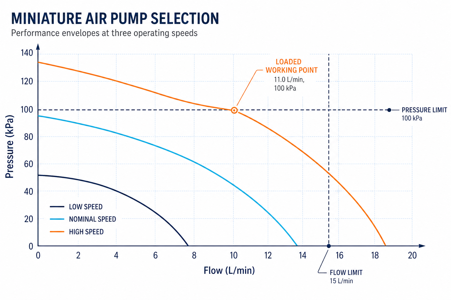
Material screening answers whether the wetted parts remain acceptable. Pump testing answers whether the assembled unit still delivers the required flow, pressure, priming and leakage performance. Run both tracks because a diaphragm may remain visually intact while its stiffness or sealing behavior has changed enough to move the working point.
For each candidate material, record initial dimensions or mass where useful, visual condition, hardness or flexibility check if available, and the change after exposure. Then assemble the exposed parts into the pump and measure flow at the actual head or back pressure. Add startup, restart after soak, steady-state current, temperature rise and leakage checks so the test can distinguish a material effect from a motor or system restriction.
Keep the test fixture close to the production fluid path. Use the final tube inner diameter and length, the intended filter, fittings, valve arrangement and reservoir condition. A material result generated with a short open tube does not prove the pump will meet flow after the real restriction is installed.
Design a soak and cycling test that reflects service
A useful EPDM vs FKM diaphragm comparison includes more than one exposure point. Define the fluid temperature, concentration, pressure state, contact duration and whether the pump is running or parked during exposure. If the equipment is cleaned between batches, include the cleaning fluid and rinse sequence instead of testing only the process liquid.
A practical sequence is to record a baseline, run the pump at the intended working point, expose it for the expected service interval, and then repeat the same measurements. Add an accelerated condition only when the acceleration method is understood and its result will be used for a defined decision. Do not turn an arbitrary high-temperature soak into a lifetime claim.
Inspect the diaphragm and valves after exposure, but do not rely on inspection alone. Measure the same flow, pressure, vacuum if applicable, current, temperature and leakage values before and after the test. A small visual change can be acceptable in one design and unacceptable in another if it causes a priming delay or a leak at the equipment's hold pressure.
Validate leakage at the real pressure and rest state
Liquid pump leakage is a system result. The source may be the diaphragm, valve seat, port seal, tube connection, reservoir interface or a crack created during assembly. Define the leak path and the acceptance method before testing. A pressure-decay test, visual inspection, mass-loss check or dyed-fluid observation may answer different questions and should not be treated as interchangeable without correlation.
Test at the pressure the equipment will hold, including the warm and cold states that change seal behavior. Also test after the pump has stopped, because a valve or diaphragm that seals while cycling may show a different result when the liquid column remains static. Record the pressure ramp, stabilization time, duration, temperature and any visible wetting location.
If the pump is used for dosing or metering, connect leakage to the equipment's measurement error. A small internal bypass can reduce delivered volume or delay priming without producing an obvious external drip. Compare delivered mass or volume, startup time and hold pressure alongside the material condition.
Convert test results into a controlled configuration
The release record should name the exact model, diaphragm material, valve material, motor, voltage, port arrangement, tube and fluid. “EPDM diaphragm approved” is incomplete if the valve, seal, adhesive, concentration or temperature limit is not attached to the same record. Configuration control prevents a material result from being reused for a different pump build.
Set acceptance limits for appearance, dimensions where relevant, flow, pressure, priming time, leakage, current and temperature rise. Add the test state for every limit: new or conditioned part, clean or loaded filter, warm or ambient fluid, continuous or intermittent duty. The limit is useful only when the production test can reproduce the same state.
Any change to fluid supplier, formulation, concentration, cleaning method, diaphragm compound, valve, tube or process temperature should trigger a review. The next action may be a document check, a short compatibility screen, a full pump validation or a new pilot lot. Make that decision visible in the change record instead of leaving it as an informal engineering comment.
A practical decision path for OEM teams
Use this sequence when a project asks for an EPDM diaphragm or FKM diaphragm configuration: first freeze the fluid and operating envelope; second map the wetted assembly; third screen the material against the real exposure; fourth measure the loaded pump working point; fifth verify leakage and restart behavior; and finally release the model, material set and test method together.
The result may be EPDM, FKM or a request for more information. That is a better engineering outcome than selecting by a generic compatibility table and discovering after pilot production that the pump cannot prime, the flow has drifted or the seal leaks after shutdown. The purpose of the comparison is not to declare a universal winner; it is to produce a configuration that can be repeated and supported.
When requesting a review, provide the fluid name and composition, concentration, temperature, pressure or vacuum, target flow, duty cycle, cleaning sequence, tubing and filter details, expected exposure time and current validation evidence. These inputs let the pump supplier connect an EPDM vs FKM diaphragm recommendation to the actual equipment decision rather than a generic catalog label.
Frequently asked questions
Is EPDM always better for water-based liquids?
No. EPDM can be a useful starting option for many water-based or aqueous services, but the formulation, concentration, temperature, cleaning fluid and exposure time still need project-specific compatibility and pump validation.
When should FKM be included in the comparison?
Include FKM when the medium, temperature or exposure condition makes oil, fuel, solvent or higher-temperature resistance part of the design question. Confirm the actual compound and test condition instead of relying on the material name alone.
Can a chemical compatibility chart replace a liquid pump test?
No. A chart can help screen candidates, but it does not reproduce the assembled pump's flexing, valve action, pressure, temperature, tubing restriction, priming or leakage behavior. The final configuration needs a loaded test.
What should be recorded in an EPDM diaphragm validation report?
Record the exact model and material set, fluid and concentration, temperature, pressure, exposure time, tubing and accessories, baseline and post-exposure flow, priming, leakage, current, temperature rise, visual condition and acceptance decision.
Does an EPDM or FKM change require a new production release?
It requires at least a documented change review. Whether a new compatibility screen, full validation or pilot lot is needed depends on the affected fluid path, working point, acceptance limits and the evidence already approved for the original configuration.
Related products and engineering resources
Continue with the products, application material and engineering support related to this topic, or submit project conditions for a selection review.