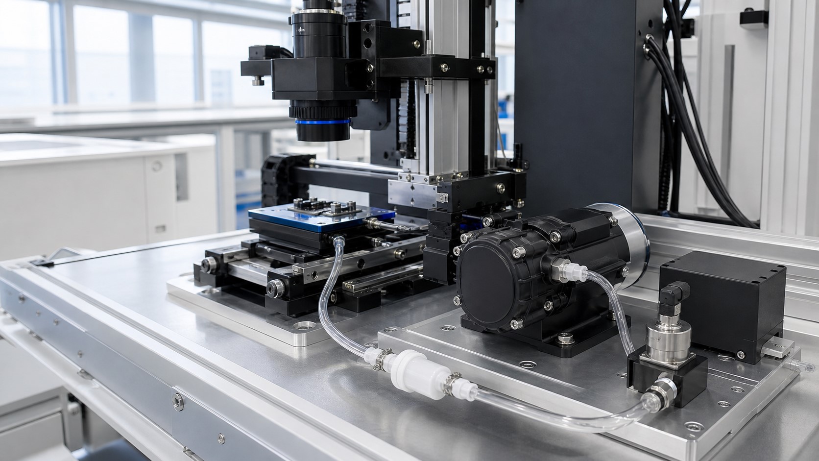
Compact case summary
Application function
◎Hold and release parts during optical inspection
Medium
~Air
Required working point
◴Defined by equipment requirement
Power and control
+DC power with on/off or PWM control
Installation constraints
◇Limited space and mounting vibration constraints
Validation focus
✓Confirmed during system test
The system requirement
- Task
- Create and hold vacuum at the fixture during inspection; release for part transfer.
- Failure modes
- Loss of vacuum, slow response, excessive noise/vibration, overheating, contamination.
- Flow-path resistance
- Vacuum point, filter, tubing, fittings, valves and sensors contribute to total resistance.
- Startup state
- Atmospheric pressure at start; system must reach working vacuum quickly.
- Noise / thermal constraints
- Low acoustic signature required; limited heat rise in a closed cabinet.
- Service access
- Filter and pump accessible for inspection; easy replacement and cleaning.
Why pump selection could not use a maximum value alone
- Free flow
- Flow rate with no load. Not the operating condition.
- Maximum vacuum
- Ultimate vacuum with no flow. Not the operating condition.
- System curve
- Represents total resistance of the actual fluid path.
- Working point
- Intersection of pump curve and system curve. This is where the system operates.
- Margin
- Margin to account for system resistance changes, component tolerance and aging. Margin must be validated.
The goal is a stable working point with confirmed margin, not the maximum value on a curve.
Configuration reviewed as a complete fluid path
- ◉Inlet fixture(vacuum point)
- ▥Filter(near the point)
- ◯Tubing(defined ID / length)
- ⌁Valve / Sensor(control & feedback)
- ▣Pump(miniature)
- ▱Exhaust(quiet or direct)
Configuration-review notes
- Short, straight tubing reduces loss and response time.
- Filter protects the pump from dust and particles.
- Valve and sensor placement affects response and stability.
- Check check valves, leak paths and sealing method.
- Exhaust method should consider noise and back pressure.
- Confirm compatibility of all components with the medium.
Interfaces that affected the result
Pump model / configuration
▧Displacement type, valve material, mounting orientation
Voltage and startup current
~Supply voltage, startup inrush, cable and connector
Tubing ID / length
/Inner diameter, total length, routing
Filter pressure loss
▥Type, location, cleanliness, replacement interval
Mounting / isolation
◇Method, vibration isolation, cabinet attachment
Control / feedback
◴On/off or PWM, feedback type, signal wiring
Ambient condition
TTemperature range, humidity, dust exposure
Interfaces above interact and should be reviewed together during selection and validation.
Prototype and validation plan
- 1▤
Bench baseline
Measure response and stability on a test rig with target components.
Evidence / DeliverableTest report, curve overlay - 2▥
Equipment installation
Install in the equipment with intended mounting and routing.
Evidence / DeliverableInstallation checklist - 3◴
Startup / load test
Verify startup time, hold and release under actual conditions.
Evidence / DeliverableOperating log - 4⌁
Noise and thermal review
Measure noise and heat rise under representative operation.
Evidence / DeliverableNoise/thermal notes - 5↻
Duty-cycle test
Run continuous duty cycle to check stability and reliability.
Evidence / DeliverableDuty-cycle summary - 6✓
Design confirmation
Confirm results and issue the final configuration recommendation.
Evidence / DeliverableFinal review record
Tell Us the Working Point, Not Just the Pump Type
Share the equipment function and real operating conditions so the pump, accessories and validation plan can be reviewed together.
Final note
The working point, system configuration and environment should be validated in the real device.
Our role is to support the engineering process and confirm suitability through transparent tests.