
Specify what the miniature liquid pump must deliver
Start with the liquid delivered at the equipment outlet, not the largest flow number in a catalog. A micro liquid pump feeding an open reservoir faces a different load from one pushing through a filter and dispensing valve. Write down the required flow, delivery time, lowest reservoir level and outlet condition before comparing models.
Distinguish continuous transfer from a timed dose. If the equipment needs 10 mL in 10 seconds, the average delivery rate during that interval is 60 mL/min. That calculation does not establish dose accuracy: startup delay, trapped air and flow after shutdown can change the delivered volume. Specify a volume tolerance separately.
Build a pressure budget at the required flow
For steady transfer between reservoirs, estimate the pump differential pressure as the destination-to-source pressure difference plus elevation head and losses in the inlet tube, outlet tube, filter and valves. Evaluate each loss at the target flow. Do not add a filter's maximum pressure rating as though it were its operating pressure drop.
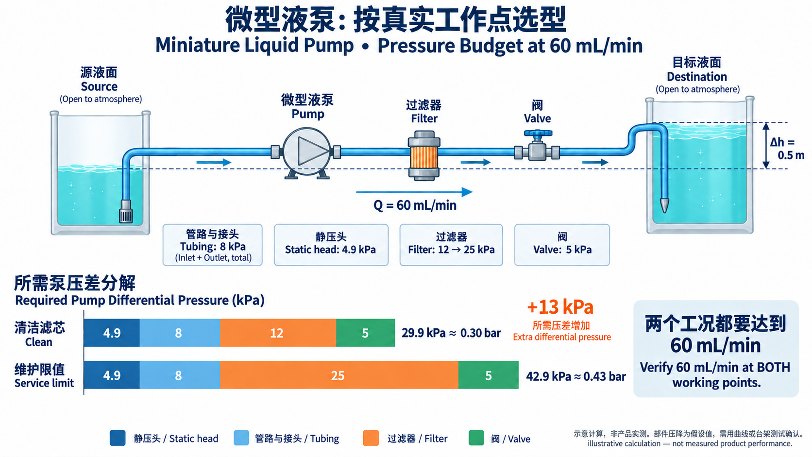
Consider an illustrative design budget, not a measured JSG product result: water must flow at 60 mL/min between two open reservoirs, with the destination liquid surface 0.5 m higher. At that flow, assume tubing and fittings lose 8 kPa, the filter loses 12 kPa and the valve loses 5 kPa. Static head is approximately 1,000 × 9.81 × 0.5 = 4,905 Pa, or 4.9 kPa. The estimated total is 29.9 kPa, about 0.30 bar.
The next question is whether a candidate delivers at least 60 mL/min at that differential pressure under the specified test conditions. If filter loss rises from 12 to 25 kPa by the service limit, the estimated total becomes 42.9 kPa, about 0.43 bar. Check this second working point as well. These assumed losses must be replaced by component curves or bench measurements before approval.
Read the curve together with its test conditions
Request the flow-versus-pressure curve for the exact motor, voltage and wetted configuration. Confirm whether the pressure axis describes outlet gauge pressure with an atmospheric inlet or differential pressure across the pump. Maximum free flow and maximum pressure are separate operating limits; they do not describe one simultaneous working point.
Water-test data is a starting point for comparison. Fluid viscosity, temperature and hose connections can change the result. Ask for confirmation with your liquid and inlet arrangement when those differ from the published setup. A supplier's operating manual, such as the KNF NF 25/NFB 25 manual, explicitly identifies these dependencies; its ratings do not establish the performance of a JSG configuration.
Test dry priming and low-level restart separately
A liquid-filled pump that meets the flow target may still fail the first fill. Define priming time from motor start to stable liquid delivery at a named observation point. Record the vertical distance from the lowest source liquid level to the pump inlet, tube length and internal diameter, outlet resistance and starting wet or dry state.
Repeat the test after a reservoir change and after the intended standby interval. If restart fails, check loose suction fittings, trapped air, valve condition and an obstructed reservoir vent before changing the motor speed. Set a timeout within the model's approved dry-running limit; self-priming capability is not permission for unlimited dry operation.
Match the liquid path and control method
For a micro diaphragm liquid pump, list the liquid, concentration, operating temperature, cleaning fluid and exposure time. Review the head, diaphragm, valves, seals and tubing as a set. Use compatibility information to shortlist materials, then test the assembled path for leakage, flow change and restart after exposure.
A stable average flow can hide pulses that matter to a sensor or dispensing step. If a damper or additional valve is proposed, repeat the volume and response-time test with that component installed. Also measure off-state leakage or siphoning in the actual reservoir arrangement. Pumping valves should not be assumed to provide a specified shutoff function unless that behavior is documented and verified.
Approve a sample against a repeatable test sequence
First establish the water baseline at nominal supply voltage and the defined working point. For gravimetric flow measurement, tare the collection vessel, collect for a measured interval and calculate Q = collected mass / (liquid density × time). Use consistent units and density at the test temperature. Record individual runs rather than only their average.
Then repeat with the real medium, minimum specified supply voltage, lowest liquid level and expected end-of-service filter resistance. Include first start, warm operation and restart after standby. Use the equipment's actual on/off timing and enclosure, recording current and temperature alongside flow. A brief open-bench run does not establish the intended duty cycle.
Before testing, agree on minimum delivered flow, maximum priming time, allowable volume error and electrical and thermal limits. In the illustrative budget above, both 0.30 and 0.43 bar conditions need a pass decision against the 60 mL/min requirement. Sample quantity, run duration and permitted variation belong in the project acceptance plan; they are not universal pump specifications.
Turn the working point into an actionable RFQ
Send the liquid and temperature range, required loaded flow, pressure budget, inlet lift, tubing layout, voltage range, duty cycle and installation envelope together. Attach the priming and volume acceptance rules if the pump must fill an empty line or deliver timed doses. Request a configuration-specific curve and identify which conditions still need sample testing.
Use the linked liquid pump collection to shortlist configurations and the technical resources page to request supporting documents. The pressure-budget illustration compares the two calculated working points; it does not show measured performance of the linked OD-05TF110W or any other model. Select a model only after the supplier confirms the working points and the prototype meets your agreed limits.
Frequently asked questions
How do I size a miniature liquid pump?
Specify the delivered flow at the full system pressure requirement, then check priming, medium compatibility and duty cycle. Use the exact configuration's curve and test the lowest liquid level and expected filter resistance before approving the model.
Are micro liquid pump and miniature liquid pump different technologies?
The labels alone do not define a pumping mechanism or a size threshold. Check whether the device is a diaphragm, peristaltic, gear or another pump design, then compare the documented flow, pressure, materials and control requirements.
Can a self-priming liquid diaphragm pump run dry continuously?
Do not infer continuous dry-running permission from self-priming. Confirm the dry-running duration and conditions for the selected configuration, and implement an appropriate priming timeout or low-level response.
Does a 12V or 24V label tell me the pump's delivered flow?
No. Voltage identifies an electrical requirement, not a working point. Compare configuration-specific curves and measure the voltage at the pump terminals under load, including the minimum supply condition expected in the equipment.
Related products and engineering resources
Continue with the products, application material and engineering support related to this topic, or submit project conditions for a selection review.